Our mission

LED Q&A thread

sfsuphysics said:
Why do you need a current fixed device (buckpuck or similar) with them and not simply a voltage source? Is it a matter of wanting to overdrive them at a fixed voltage (are you even doing that?).

How close can you pack these buggers?

Just a little more clarity.

(numbers for illustrative purposes. not exact)
First, Vf is variable, but for a given bin, the output (lumens) maps well to current.

here are some numbers:

A 10% increase in Vf (3-->3.3) results in a 220% current increase (250mA-->800mA) and a 133% output increase. (75 lumens-->175 lumens)

lesson: If you supply equal voltage without hand matched Vf's, you will have LEDs being driven to VERY different current levels and as a result will have VERY different output levels between LEDs.


To answer your second question (which I failed to do earlier :() You can pack them very close together...if you can pull the heat away. MC-E's have 4 emitters under on a single package. Some manufactures took this idea and do crazy things like 10x10 emitter arays over a square cm. Nothing wrong with this...if you can pull the heat away!
 
Out of curiosity how do you get that current increase? I'm fairly sure they're not ohmic devices, hell I can tell from the numbers you gave, but is there some sort of plug and chug formula? Almost look exponential, I'm guessing the resistance becomes a function of voltage or something strange like that.
 
I don't know enough about semiconductor physics to tell you. I pulled information from plots on Cree's data sheets :)

At the time, I had the XP-E royal blue spec sheet up
http://www.cree.com/products/pdf/XLampXP-Ecolor.pdf
 
I see, well looking at that spec sheet, and I might be reading it wrong but one of the graphs looks to show you can still see 80% of the luminosity at a 45°, that doesn't sound too shabby for distribution.
 
Please help me understand, what would be the difference between a DC power supply for LED's and a LED Driver.
If I have couple LED at let's say 6V each (Just a saying) and run at 750 Ma and a power supply that provides 6V and 1500Ma will it be OK to use or a Driver same voltage/amp?

Thx
 
A DC power supplies a fixed* voltage (ie always 12V) and draws whatever current is necessary to make this happen. An LED Driver is a regulated current source (ie, always gives 700 mA) and varies voltage to meet that current need.

Almost every device you use are voltage devices. LEDs are current based devices.


*you hook a 12V DC powersupply up and you supply 12V and get whatever current your device pulls (assuming the powersupply can supply it). Some DC power supplies like laptop powersupplies are regulated (ie, always give 12) but most are unregulated (give approximately 12V...it varied a bit with current draw).

This isn't the WHOLE picture, but it is enough without getting super technical.


Part 2 of your question. When you see a typical AC adapter, it might say 9V, 700mA. It is almost certain that it is 9V unregulated and can supply up to 700 mA. DO NOT mistake this in any way shape or form as a 700mA source for LEDs...or you will kill your LED. You want a powersupply which is specifically a current source, like the Xitanium or Luxdrive current sources. You would choose a 700mA source. These usually can power 1-6 LEDs in series. (parallel is unstable and divides the current)
 
here's another Q.

How many of what type (power) LEDs would be required to replicate say a 175W MH lamp of 20000K spectrum.

I just shot out 175W because its a low wattage halide (relatively speaking), and to maybe get a feel for how many LEDs are required to get that kind of light output.
 
A bit of guestimating here since I'm running on limited experience. You'll probably find that you need 40-50% of the power equivelent in an LED setup. So, for 175watts, you'll need something like
175/(2*3.5*0.7)=36 leds (with optics for non AIO cube tanks)
..based on Q5 experience


For 20kk, you will need something like 60% royal blue. Almost every fixture I see made is 50/50 though and people seem pretty darn happy with that mix.

I'll eventually be doing a 50/50 array using 18 white and 18 blue
 
36 x 2.5= 90 watts which is about 1/2 the 175 watt. The 2 in the equation is from my experience of LEDs being a lot more efficient at getting light into the tanks. I'd be VERY confident in a 6white/6blue LED retro (30 watts) without optics being a significant improvement to my 70watt MH sunpod.
 
it depends on the driver. Some can only power 1 LED at ___ current. 6 and 12 are common though. Usually, it is something like 3-6 on xitanium drivers (700ma) and 1-8 on their 350mA. the meanwells I believe do something like 6-12.
 
Sweet! I get to ask myself a question!


Q: So now that I have one of those new Meanwell ELN-60-48-P drivers, how do I use them properly?!?!

A: welll, there are a few things you need to know about this driver to implement it


1) LED string limits: These drivers have a minimum and maximum # of LEDs you can run on them. For those running the Crees from the group buy, you want to run between 6 and 13 LEDs. NO MORE than 13 and NO LESS than 6.
Doing so is unstable and will result in fried LEDs and/or driver.

2) The drivers have an adjustable maximum outout control. Unless someone wants to push the limits, eveyone should open up their driver (4 small screws) and locate an adjustable pot labeled SVR2 (NOT SVR1). Turn this pot CounterClockwise till it stops (don't over tighted). This should set the MAXIMUM driver output to -25% of the original max. --> 1.3A * 0.75 = 0.98A. If you have a multimeter, double check this. 0.98A is an estimate.

3) Most people may want to just turn the LEDs on and off and to do this, you just need to supply 10V to the dim wires. if you supply no voltage, the drivers will not turn on your LEDs. You can decide if you want to turn on and off your LEDs by putting the driver or dim power on a timer.
IMPORTANT: You can probably supply less than 10V in the range of 8-10V. I haven't tested this, but it is reported at 5V is too low. You can't supply more than 10.6V or it will damage the dimming circuit.
IMPORTANT: Typical wallwarts are unregulated. The indicated output on them are not what they put out. A typical 12VDC wall wart can put out 10-14V or so depending on their load. If you are using a wallwart, I would try something like an 8VDC wallwart unless you have a regulated one.

If you want to dim the drivers...this is where it gets fun. It is really a lot easier than it sounds. These drivers use a Pulse Width Modulated (PWM) digital signal to dim. The input requires a 10V signal with modulation frequency ranging from 100hz to 3khz. A duity cycle of 11% will result in 15% current output (minimum controllable level) and 100% will result in 95% current output (maximum controllable level) If you are using two drivers, you can separate your white and blue LEDs on different drivers and use PWM to control their relative value and thus change the "color" of your tank ranging from >20,000K to around 6,000K


How to do PWM? well, someone on another forum has already done a fair bit of work for us.
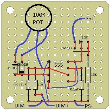
Here is his design which I trust works perfectly. The parts are available at your local radioshack and should be pretty cheap. You need one per independently controlled driver

555PWM.jpg

Black lines are component leads
Red lines are bottom side solder traces
Blue lines are top side wires

Use a 12v or greater (up to 32v) power supply for this. A 12VDC wallwart should work perfectly fine for this. You hook the wallwart up to the +/- PS points


Hope this helps! If you have questions, feel free to ask
 
Great write up tony,
Do you know if there is a way to get the pot on a remote control? I'm thinking about using the rest of my lights to make a fixture, I think it would be pretty cool to have a remote control on it.
 
apparently from what i've read it's possible just have to steal the remote and receiver from a tv and hook it up to the pot because a volume potentiometer is similar.
 
Heads up on the meanwells. I followed the instructions with turning SRV2 counterclockwise to set to 1amp (-25%) but this isn't actually what happened.

With all three drivers, all the way counter clockwise resulted in about 250mA as the max output. I had to manually adjust the SRV2 pot with the aid of a DMM to set the max at 1amp.
 
You should be able to use a single powersupply for several PWM circuits in parallel.
http://www.radioshack.com/product/index.jsp?productId=2062587 should work fine for the diode.
http://www.radioshack.com/product/index.jsp?productId=2062287 should be fine for the pot (pretty sure you want a linear taper and not a log)

If you have the time, I'd advise you check out this long and evolving thread.
http://www.nano-reef.com/forums/index.php?showtopic=183692
 
Back
Top